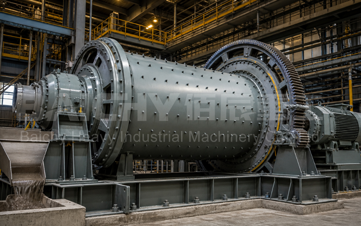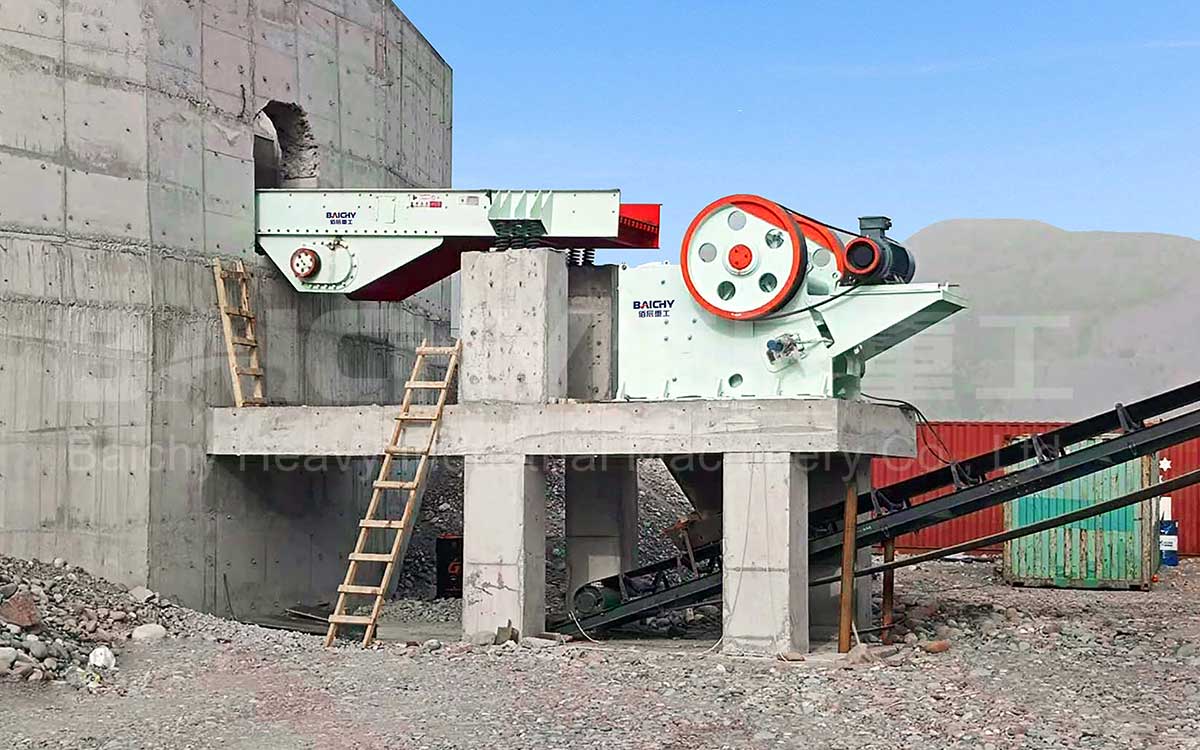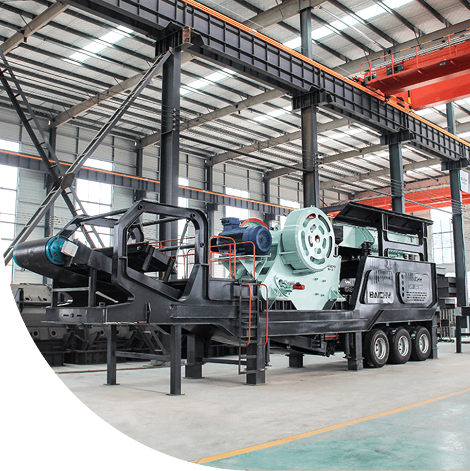

Vibrating feeder production line site
Project Overview
| Item | Details |
| Equipment Model | ZSW1100×4200 Vibrating Grizzly Feeder (Heavy-duty) |
| Application Scenario | Front-end feeding for 150–300 tph primary crushing lines (limestone, granite, basalt, iron ore, river pebbles, etc.) |
| Compatible Primary Crusher | PE750×1060 / PE900×1200 Jaw Crusher (Primary Crushing) |
| Trough Dimensions | 1,100 × 4,200 mm |
| Max. Feed Size | ≤ 580 mm (blasted raw stone) |
| Processing Capacity | 200–430 t/h (Standard: 15 kW); 300–500 t/h (Heavy-duty: 22–37 kW) |
| Core Functions | Uniform, metered feeding + Grizzly pre-screening (fines ≤80 mm bypassed, not entering crushing chamber) |
| Manufacturer | Baichy Heavy Industry |
Key Takeaway: The ZSW1100×4200 vibrating feeder is a primary crushing front-end unit that combines feeding and pre-screening. It allows loaders or dump trucks to discharge directly, ensuring uniform and metered feeding into the jaw crusher. Simultaneously, the grizzly screen removes 15–25% of fines and soil from the raw ore before it enters the crushing chamber. This reduction in the jaw crusher's actual workload translates directly to lower jaw plate wear, reduced specific energy consumption (kWh/ton), and higher effective production capacity. For a target line capacity of 150–300 tph, this model offers over 30% excess capacity, representing a highly reliable "heavy-duty equipment for lighter-duty tasks" selection.
I. Equipment Purpose and Operating Parameters
Fines passing through the grizzly bars (material smaller than the bar gap) are discharged directly via an independent chute or bypass conveyor, bypassing the crushing circuit.
1.2 Applicable Materials and Operating Parameters
| Item | Boundary Conditions |
| Applicable Materials | Limestone, granite, basalt, diabase, iron ore, river pebbles, construction waste, etc. |
| Material Bulk Density | 1.4–2.6 t/m³ (rated capacity based on 1.6 t/m³; conversion required for different densities) |
| Feed Size | ≤ 580 mm; occasional oversized pieces (>580 mm) require pre-treatment via grizzly screen or hydraulic hammer |
| Moisture Content | Dry material is optimal; if moisture >8% and clay content is high, grizzly bars may clog—gap adjustment or a grizzly screen is required |
| Electrical Standards | 380V/50Hz standard; customizable to 400V/50Hz, 440V/60Hz, 380V/60Hz, 460V/60Hz |
II. Main Technical Parameters
| Parameter | Value | Remarks |
| Model | ZSW1100×4200 | 1100 mm (width) × 4200 mm (length) |
| Trough Dimensions | 1,100 × 4,200 mm | Heavy-duty welded steel plate structure; capable of direct unloading from loaders |
| Max. Feed Size | ≤ 580 mm | Occasional oversized pieces require pre-treatment |
| Processing Capacity | 200–430 t/h (Standard) | Heavy-duty: 300–500 t/h (depending on material and bar gap) |
| Motor Power | 15 kW (6-pole) | Heavy-duty options: 22 / 30 / 37 kW |
| Exciter | Dual eccentric shaft forced synchronous vibration | Gear meshing ensures synchronous counter-rotation of the two eccentric shafts |
| Amplitude | 8–10 mm (adjustable) | Excitation force adjusted via counterweights |
| Vibration Frequency | ≈ 960 r/min | 6-pole motor with V-belt drive |
| Installation Inclination | 0° (Horizontal installation) | No need for a sloped civil engineering ramp; simple foundation |
| Grizzly bar spacing | 60–100 mm (adjustable) | Integrated bar assembly; bolted fixation |
| Overall dimensions (L×W×H) | ≈ 4,300 × 1,780 × 1,210 mm | Reference value; subject to manufacturing drawings |
| Total weight | ≈ 9,000 kg | Reference value; subject to factory specifications |
Note: The above parameters apply to the standard model. The heavy-duty model (22–37 kW motor; throughput 300–500 t/h) is suitable for continuous unloading from large mining trucks and high-density hard rock applications; final specifications are subject to drawings confirmed in the technical agreement.
III. Structure and Working Principle
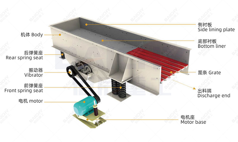
Vibrating Feeder Structural Diagram
3.1 Structural Components
| Component | Description |
| Feed trough | Heavy-duty welded steel plate construction; discharge outlet features wear-resistant liners; impact-resistant design |
| Grizzly screen deck | High-manganese/wear-resistant steel bars; adjustable spacing; performs pre-screening |
| Exciter | Dual eccentric shafts + meshing gears; forced synchronous counter-rotation generates directional excitation force |
| Drive system | Motor + V-belts + pulleys; connects to the exciter |
| Support system | 4–6 sets of vibration-damping coil springs; isolates vibration transmission to the foundation |
| Base | Welded steel structure; connected to the concrete foundation via anchor bolts |
3.2 Working Principle
The motor drives the exciter via V-belts. Two eccentric shafts are forced to rotate synchronously in opposite directions through meshing gears. The centrifugal forces generated by the two sets of eccentric weights cancel each other out in the horizontal direction and combine in the vertical direction, creating a stable, directional linear excitation force. Under this force, the feed trough undergoes high-frequency reciprocating vibration in the vertical direction; material is continuously tossed and slides forward, achieving uniform, continuous, and controllable feeding.
During this process, fine materials, soil, and debris smaller than the grizzly bar spacing fall directly through the gaps and are discharged via a bypass—this constitutes the core mechanism of the "feeding + pre-screening" 2-in-1 function.
3.3 Key Design Features
• Forced synchronization via dual eccentric shafts: Compared to single-shaft excitation, the direction of the exciting force is stable and free from drift, resulting in superior material flow uniformity; suitable for handling large, heavy-duty materials.
• Heavy-duty trough: Capable of withstanding the impact of large material loads dumped directly from loaders or dump trucks, eliminating the need for intermediate buffer hoppers and saving on civil engineering costs.
• Spring-based vibration isolation: Vibrations are absorbed by springs, minimizing the load transmitted to the foundation; a standard concrete foundation is sufficient to meet requirements.
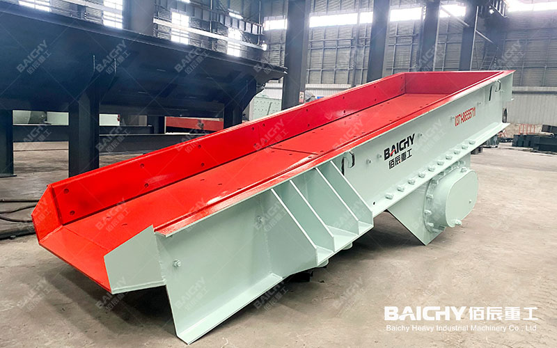
Vibrating Feeder Display Diagram
IV. Model Selection and Matching Recommendations
4.1 Matching Principles for Jaw Crushers
| Matching Item | Requirement |
| Feeder trough width | ≥ Jaw crusher feed opening width (1100 mm ≥ 750 mm; suitable for PE750×1060) |
| Feeding capacity | ≥ Target production line capacity × 1.3 (30%+ redundancy) |
| Max. feed particle size | Feeder max. feed size ≤ Jaw crusher max. feed size (580 mm ≤ 630 mm; compatible) |
| Discharge height | Aligned with jaw crusher feed opening; install wear-resistant chute/guide plate at the discharge point |
4.2 Typical Equipment Configurations (by Production Line Scale)
| Production Line Target | Feeder | Jaw Crusher | Secondary/Fine Crushing |
| 150–250 tph | ZSW1100×4200 (15 kW) | PE750×1060 | CS160 / PF1315 |
| 250–300 tph | ZSW1100×4200 (Heavy-duty: 22–37 kW) | PE750×1060 / PE900×1200 | HP300 / PFW1315 |
4.3 Optional Accessories
• Suspended magnetic separator (RCYD series): Removes iron from above the conveyor belt or chute to prevent metal from entering the crushing chamber (highly recommended; essential for ore or construction waste applications);
• Variable Frequency Drive (VFD): Enables stepless adjustment of feed rate; integrates with material level sensors and crusher current monitoring for automatic flow control;
• Material level sensor: Monitors levels in the hopper/trough and links to feeder start/stop functions to prevent no-load operation or overloading;
• Bypass conveyor: Independently conveys fines screened out by the grizzly bars; material can be sent directly to the finished product stockpile or discharged as waste.
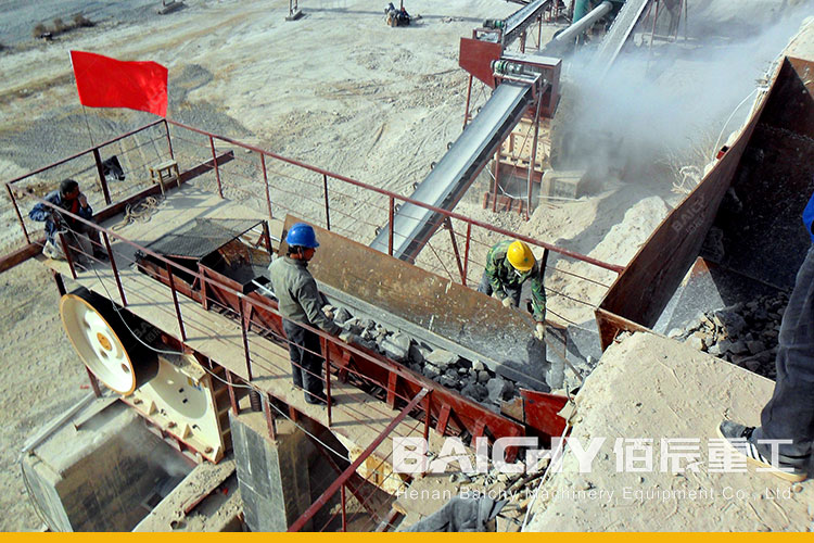
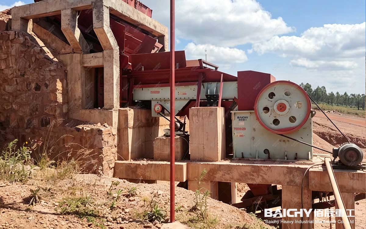
Vibrating feeder operation site
V. FAQ
Q1: What is the difference between the ZSW series and the GZD series?
A: The ZSW is a heavy-duty grizzly feeder featuring a wide, impact-resistant trough and integrated grizzly bars for pre-screening; it is designed to handle large, hard rocks and direct unloading from loaders. The GZD is relatively lighter and typically configured for continuous, uniform feeding. The ZSW is the preferred choice for primary crushing stages, while the GZD or electromagnetic feeders are suitable for lower-throughput sections like milling or mineral processing.
Q2: Can the ZSW1100×4200 handle direct unloading from a loader? Is an intermediate hopper required?
A: Yes. The heavy-duty trough is designed to withstand direct unloading from loaders or dump trucks, eliminating the need for an intermediate hopper. The recommended unloading height is ≥2.5 m, with the drop point aligned with the middle-to-rear section of the trough to avoid direct impact on the discharge outlet.
Q3: Can the feed rate be adjusted?
A: Yes. On standard models, the feed rate is adjusted by changing the vibration amplitude (8–10 mm) via the exciter's counterweights. With an optional variable frequency drive (VFD), stepless speed control is possible, enabling automatic flow regulation through interlocking with material level sensors and the crusher's motor current.
Q4: Can the grizzly bar spacing be adjusted? How?
A: Yes. The grizzly bars form an integrated assembly secured by bolts, allowing the gap to be adjusted within the 60–100 mm range. Reduce the gap for finer pre-screening, or increase it when handling wet, sticky materials.
Q5: My production line capacity is only 150 tph; is it wasteful to use a feeder rated for 200–430 t/h?
A: No, it is not wasteful; this is a choice made for reliability. A low feeder load ratio translates to a longer service life and extended maintenance-free intervals, while also allowing the unit to handle sudden peak loads (such as the impact of a 5–8 ton bucket load from a loader). The feeder is the least expensive component of the entire line, yet it is the one link where a bottleneck should absolutely be avoided.
Q6: Can the motor voltage and frequency be customized?
A: Yes. Standard configuration is 380V/50Hz; customization is available for 400V/50Hz (South Africa/Southeast Asia), 440V/60Hz, 460V/60Hz (North America), 380V/60Hz (Brazil), etc. The entire system is selected to match the local power grid, avoiding compromise solutions that pair a 50Hz motor with a variable frequency drive.