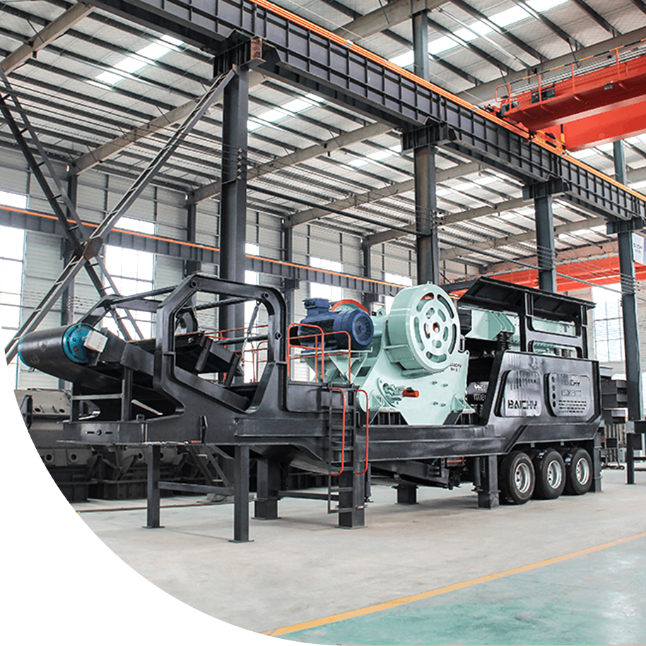

For small-to-medium-scale hard-rock gold mines with a daily capacity of 100 tonnes (approx. 4–5 t/h), the "two-stage crushing + single-stage closed-circuit grinding + CIL (Carbon-in-Leach) + high-temperature/high-pressure desorption-electrolysis" whole-slurry cyanidation process represents the optimal technical route. It balances investment cost-effectiveness (equipment investment of approx. USD 350,000–550,000) with high recovery rates (90%–95%). This article provides a comprehensive equipment selection list, technical parameters for each stage, itemized CAPEX/OPEX estimates, and an EPC implementation roadmap to assist mine owners in completing the full project cycle—from infrastructure construction to commissioning—within 3 to 6 months.
Note: According to the *USGS Mineral Commodity Summaries 2026*, global gold production in 2025 was approximately 3,300 tonnes. Small-to-medium-scale (50–500 t/d) CIL/CIP processing plants account for a significant share of global gold production capacity.
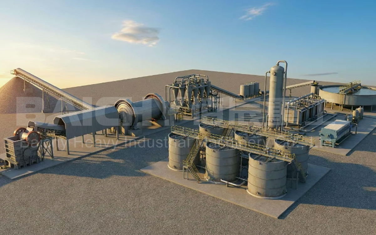
Figure 1: Panoramic layout of the 100-ton-per-day CIL gold concentrator plant—the complete equipment chain from raw ore silo to tailings treatment
1. Overview of the CIL Process Flow
1. Run-of-mine (ROM) bin + feeding
2. Primary crushing (jaw crusher)
3. Secondary crushing (fine jaw crusher)
4. Ball milling + classification
5. CIL leaching and adsorption
6. Desorption and electrolysis
7. Smelting and ingot casting
8. Tailings treatment
The 100 t/d CIL production line adheres to the core principles of "fine crushing, uniform grinding, and thorough leaching." ROM ore (particle size ≤350 mm) undergoes two-stage jaw crushing to reduce the size to ≤25 mm. It is then fed into a ball mill operating in a closed circuit with a spiral classifier; the ore is ground to a fineness where 85%–95% of particles pass through a 200-mesh screen before entering the CIL leaching system. In a series of 5–6 leaching tanks, the slurry comes into simultaneous contact with sodium cyanide solution and activated carbon. Gold dissolves into Au(CN)₂⁻ complex ions and is adsorbed onto the activated carbon. Gold-loaded carbon undergoes desorption and electrolysis to yield gold sludge, which is finally smelted into ingots. Tailings slurry undergoes cyanide destruction followed by pressure filtration for dry stacking.
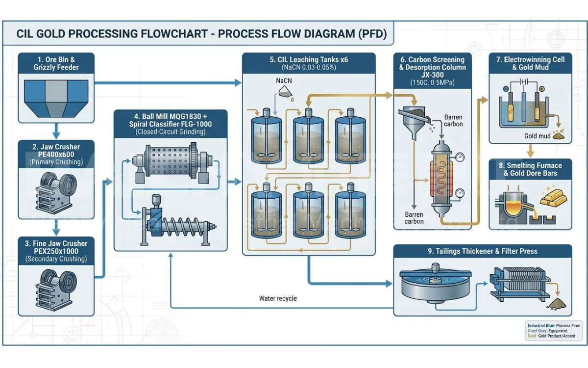
Figure 2: CIL gold processing flow—nine core stages ranging from mining and crushing to gold ingot casting.
2. Core Equipment Configuration Table (Daily Capacity: 100 Tons)
| Section | Equipment Name | Model/Specification | Quantity | Power (kW) | Key Parameters |
| Feeding & Crushing | Vibrating Feeder | GZD-850×3000 | 1 unit | 2×1.5 | Feeding capacity 30–80 t/h; trough width 850 mm |
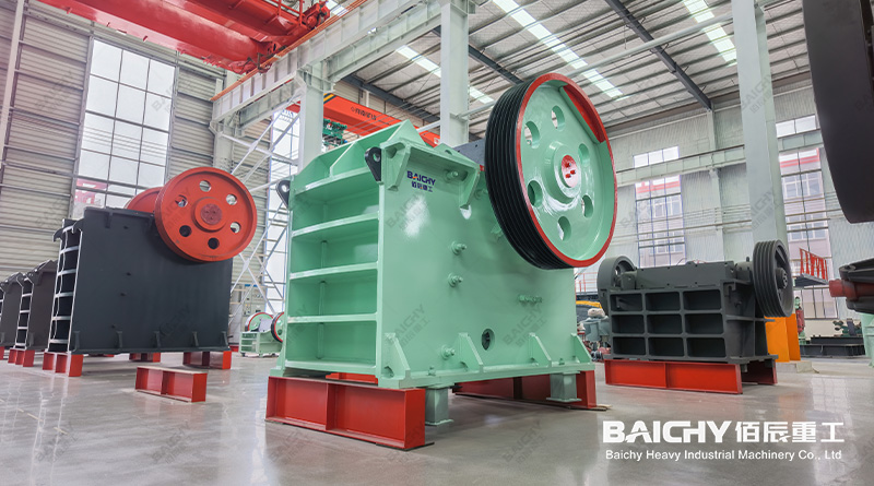
| Jaw Crusher (Primary) | PE400×600 | 1 unit | 30 | Feed opening 400×600 mm; discharge 40–100 mm; throughput 15–50 t/h | |
| Jaw Crusher (Fine) | PEX250×1000 | 1 unit | 30 | Feed opening 250×1000 mm; discharge 15–50 mm; throughput 10–32 t/h | |
| Grinding & Classification | Wet Grate-Discharge Ball Mill | MQG1830 | 1 unit | 210 | Shell Φ1.83×3.0 m; effective volume 6.5 m³; ball charge 11 t |
| High-Weir Single-Spiral Classifier | FLG-1000 | 1 unit | 5.5 | Spiral diameter Φ1000 mm; sand return 2.5–6 t/h; overflow particle size -200 mesh | |
| CIL Leaching & Adsorption | CIL Leaching/Adsorption Tank | SJ-3.0×3.5 | 6 units | 6×7.5 | Φ3.0×3.5 m; effective volume 22 m³; dual-impeller aeration & agitation |
| Carbon-Slurry Interstage Screen | ZS-600×1800 | 5 units | 5×0.75 | Screen slot 0.5–1.0 mm; prevents activated carbon migration between stages | |
| Sodium Cyanide Dosing System | JY-500L | 2 sets | 2×0.55 | Metering pump for precise dosing; automatic concentration adjustment | |
| Activated Carbon Addition & Extraction Unit | TC-300 | 1 set | 1.5 | Coconut shell activated carbon; particle size: 6–12 mesh; iodine value: ≥950 mg/g | |
| Desorption & Electrolysis | High-temperature, high-pressure desorption column | JX-300 | 1 unit | - | Φ300×1200 mm; operating pressure: 0.4–0.6 MPa; temperature: 150°C |
| Electrolytic cell | DJ-200 | 1 uni | 15 | Steel wool cathode; voltage: 3–4.5 V; current density: 20–30 A/m² | |
| Electric thermal oil heater | DR-24kW | 1 unit | 24 | Provides a stable heat source for the desorption system | |
| Smelting | Medium-frequency induction melting furnace | ZP-25 | 1 unit | 25 | 25 kg/batch; max. temperature: 1600°C; graphite crucible |
| Pregnant/Barren solution circulation pumps | Corrosion-resistant chemical pumps | 4 units | 4×3 | Fluoroplastic alloy material; resistant to alkaline slurry with pH > 12 | |
| Tailings treatment | High-efficiency thickener | NZ-6 | 1 unit | 1.1 | Φ6 m; center drive; underflow concentration: 40–50% |
| Chamber filter press | XMY60/800-UB | 1 unit | 4 | Filtration area: 60 m²; filter cake moisture content: ≤25% | |
| Auxiliary equipment Belt conveyors | B500/B650 | 5 units | 5×4–5.5 | Belt width: 500/650 mm; nylon conveyor belt (EP100) |
3. Technical Breakdown of Key Process Stages
3.1 Crushing Stage: Two-stage jaw crushing—handling hard rock with ease
To accommodate the Mohs hardness (6–8) of the lode gold ore, a two-stage jaw crushing configuration is selected, connecting a PE400×600 primary crusher (coarse crushing) in series with a PEX250×1000 secondary crusher (fine crushing). This reduces run-of-mine ore (≤350 mm) to a feed size of ≤25 mm for the grinding mill. The jaw plates are made of Mn18Cr2 ultra-high manganese steel, offering a wear life of ≥1200 hours. The PEX fine-crushing jaw crusher features a unique deep, curved crushing chamber design that produces a more uniform discharge size, thereby reducing energy consumption caused by "over-grinding" in the subsequent ball mill stage.
| PE400×600 Coarse Crushing | PE400×600 Coarse Crushing | PEX250×1000 Fine Crushing |
| Feed Size: ≤350mm | Discharge Size: 40–100mm | Feed Size: ≤210mm |
| PEX250×1000 Fine Crushing | Total Crushing Ratio | Jaw Plate Material |
| Discharge Size: 15–25mm | 14:1 – 20:1 | Mn18Cr2 |
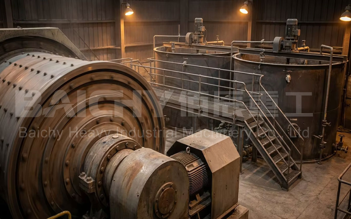
3.2 Grinding and Classification Section: Single-stage closed-circuit operation with controllable fineness
The MQG1830 grate-discharge ball mill and the FLG-1000 spiral classifier form a closed-circuit grinding system. The ball mill operates with a grinding media charge of 11 tons (graded sizes: Φ100/80/60mm) and a throughput of 4–6 t/h (based on 90% passing -200 mesh). The classifier overflow fineness is adjustable; by regulating the spiral blade rotation speed and the overflow weir height, the classification size is precisely controlled to achieve 85%–95% passing -200 mesh. Coarse sand flows back from the classifier's return port to the ball mill for regrinding; this closed-circuit loop ensures that the particle size meets specifications before entering the CIL system, thereby preventing gold loss associated with coarse particles. Relationship between grinding fineness and recovery rate (empirical data):
- 70% passing -200 mesh → Leaching rate approx. 82%–87%
- 85% passing -200 mesh → Leaching rate approx. 90%–93%
- 95% passing -200 mesh → Leaching rate approx. 93%–97%
(Specific figures subject to beneficiation test results; ultrafine grinding is required for fine-particle encapsulated gold.)
3.3 CIL Leaching and Adsorption Section: 6-stage series configuration with progressive enrichment
For a daily capacity of 100 tonnes, six SJ-3.0×3.5m leaching/adsorption tanks are configured to operate in series, providing a total effective volume of approximately 132 m³; pulp density is maintained at 40%–45%, and total residence time is approximately 24–30 hours. Sodium cyanide concentration is maintained at 0.03%–0.05% (300–500 ppm), and pH is adjusted to 10.5–11.5 using lime. [4] Activated carbon (coconut shell-based, 6–12 mesh) flows counter-currently to the pulp—fresh carbon is added at the final stage and moves forward stage-by-stage, with gold loading progressively enriching from 50–100 g/t at the tail end to 2,000–5,000 g/t at the head end. Inter-stage screens prevent carbon particles from migrating into the next stage along with the pulp.
3.4 Desorption and Electrowinning Section: High-temperature, high-pressure, efficient gold stripping
Gold-loaded carbon is fed into the JX-300 desorption column. Under high-temperature and high-pressure conditions (150°C, 0.5 MPa), a desorption solution containing 1% NaOH and 0.2% NaCN is circulated to strip the gold over 8–12 hours, achieving a gold desorption rate of ≥99%. The gold-rich pregnant solution enters the DJ-200 electrowinning cell, where gold sludge is deposited on stainless steel wool cathodes under 3–4.5 V DC; the electrowinning tail solution (barren solution) is returned to the desorption system for reuse. Each batch processes approximately 200–300 kg of gold-loaded carbon; gold sludge yield depends on the gold loading.
<<Gold All-in Sustaining Costs (AISC)." World Gold Council, 2025-2026>>
4. CAPEX and OPEX Investment Analysis
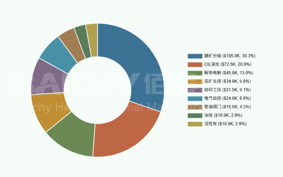
4.1 Equipment Investment (CAPEX) – FOB Chinese Port
| Section Major | Major Equipment | Estimated Cost (USD) |
| Crushing Section | GZD feeder, PE400×600, PEX250×1000, belt conveyor | 28,000 – 35,000 |
| Grinding & Classification Section | MQG1830 ball mill, FLG-1000 classifier, steel balls | 95,000 – 115,000 |
| CIL Leaching Section | 6 SJ leaching tanks, inter-stage screens, reagent dosing system, agitators | 65,000 – 80,000 |
| Desorption & Electrolysis Section | Desorption columns, electrolysis cells, thermal oil heater, circulation pumps | 40,000 – 50,000 |
| Smelting Section | Medium-frequency smelting furnace, crucibles, casting molds | 8,000 – 12,000 |
| Tailings Treatment | Thickener, filter press, slurry pumps | 30,000 – 38,000 |
| Electrical & Automation | Power distribution cabinets, PLC control system, cable trays | 20,000 – 28,000 |
| Piping & Valves | Slurry piping, cyanide-specific valves, steel platforms | 12,000 – 18,000 |
| Initial Activated Carbon | Charge Coconut shell activated carbon (6–12 mesh), approx. 3–5 tons | 8,000 – 12,000 |
Note: The above figures represent ex-factory equipment prices. Costs for sea/land transport, customs duties, civil works, and installation are calculated separately. Actual prices vary based on ore characteristics (e.g., whether pre-soaking or pre-treatment is required), metallurgical test results, the level of automation, and delivery schedules.
4.2 Operating Costs (OPEX) – Per Ton of Ore
| Cost Item | Specific Consumption | Unit Price | Cost per Ton (USD) | Proportion |
| Electricity | 35–45 kWh/t | $0.08–0.15/kWh | 2.80 – 6.75 | 20–30% |
| Sodium Cyanide | 0.5–1.5 kg/t | $2.0–3.0/kg | 1.00 – 4.50 | 10–20% |
| Lime (pH adjustment) | 2–5 kg/t | $0.10–0.15/kg | 0.20 – 0.75 | 2–4% |
| Activated Carbon | 0.03–0.06 kg/t | $2.5–3.5/kg | 0.08 – 0.21 | 1% |
| Steel Ball Consumption | 0.8–1.5 kg/t | $0.7–1.0/kg | 0.56 – 1.50 | 5–8% |
| Jaw Plate/Liner Wear | 0.02–0.04 kg/t | $2.0–3.0/kg | 0.04 – 0.12 | ≤1% |
| Labor | 8–12 persons/shift | Depends on local wages | 1.50 – 4.00 | 10–20% |
| Assay/Analysis | - | - | 0.30 – 0.80 | 2–4% |
| Others (Water/Maintenance/Admin) | - | - | 0.50 – 1.50 | 5–8% |
| Total (OPEX per Ton of Ore) | ≈$7–20 |
Note: Electricity costs vary by location (e.g., diesel-generated power at African mine sites can exceed $0.25/kWh), and labor costs also vary significantly by region. The figures above represent a reference range.
4.3 Break-even Analysis
Based on a raw ore grade of 5 g/t, a recovery rate of 90%, and a gold price of $1,800/oz: [7]
Daily gold production = 100 t × 5 g/t × 90% ÷ 31.1 g/oz ≈ 14.5 oz/day
Daily output value ≈ 14.5 × $1,800 = $26,100
Daily operating cost ≈ 100 t × $12/t (median value) = $1,200
Daily gross profit ≈ $24,900
Equipment investment payback period ≈ $400,000 ÷ ($24,900 × 300 days) ≈ 1.6 months (excluding civil works and installation)
Total investment payback period (including civil works and installation, approx. $700,000) ≈ 2.8 months
5. EPC Implementation Path and Delivery Schedule
| Stage | Content | Duration |
| Step 1: Mineral Processing Tests | Client sends 50–100 kg ore samples to Baichy's laboratory; completion of ore characterization, grinding fineness tests, and cyanidation leaching condition tests | 10–15 days |
| Step 2: Scheme Design & Quotation | Preparation of Process Flow Diagram (PFD), equipment list, layout plan, and formal commercial quotation based on test reports | 7–10 days |
| Step 3: Equipment Manufacturing | Initiation of manufacturing for jaw crushers, ball mills, leaching tanks, desorption systems, etc., following contract signing | 45–60 days |
| Step 4: Civil Construction | Client completes local civil engineering works, including plant foundations, equipment foundations, thickener tanks, tailings ponds, reagent storage, etc. | 30–45 days |
| Step 5: Logistics & Shipping | Shipment via container or bulk carrier; transit time depends on destination (Southeast Asia: 15–20 days; Africa: 30–45 days; South America: 35–50 days) | 15–45 days |
| Step 6: Installation & Commissioning | Baichy engineers provide on-site guidance for installation, single-unit testing, integrated system testing, and trial production with ore feed. | 30–45 days |
| Step 7: Achieving Target Production & Standards | Optimize process parameters and train operators until the plant operates to standard for 72 consecutive hours. | 7–15 days |
| Total cycle from contract signing to commissioning Approx | 3–6 months |
6. Frequently Asked Questions (FAQ)
Q1: What is the approximate total investment for a CIL gold processing plant with a daily capacity of 100 tons?
Equipment investment (FOB China port) is approximately US$350,000–$550,000. Including civil works/foundations, installation and commissioning, logistics, and initial stocks of reagents and activated carbon, the total EPC (Engineering, Procurement, and Construction) cost ranges from US$500,000 to $800,000. The exact figure depends on ore hardness, required grinding fineness, automation level, and project location. We recommend sending ore samples for beneficiation testing before providing a precise quotation.
Q2: What is the difference between CIL and CIP processes? Which one should be chosen for a 100 t/d capacity?
In CIL (Carbon-in-Leach), leaching and adsorption occur simultaneously in the same tank—sodium cyanide and activated carbon are added to the leaching tank at the same time. In CIP (Carbon-in-Pulp), leaching and adsorption are separate stages performed in different tanks. For a 100 t/d scale, CIL offers distinct advantages: fewer leaching tanks (5–6 tanks vs. 7–8 for CIP), shorter total residence time (24–30 hours vs. 36–48 hours), reduced carbon attrition, and lower investment and footprint requirements. It is particularly suitable for ores containing carbonaceous matter or "preg-robbing" organic carbon, as the activated carbon "competes" with the organic carbon in the ore to capture dissolved gold early in the process.
Q3: If the ore also contains silver, can CIL recover it simultaneously?
Yes. In the CIL process, cyanide dissolves both gold and silver. However, note that the leaching rate of silver is generally slower than that of gold, and silver-cyanide complexes are less stable; therefore, a higher sodium cyanide concentration (0.08%–0.12% NaCN) and a longer residence time (36–48 hours) may be required. In the electrolysis section, both gold and silver deposit onto the steel wool cathode; if the silver content in the gold sludge is high, a silver separation step must be added during subsequent refining.
Q4: Are there specific water quality requirements for the CIL process?
Yes, there are strict requirements. High-salinity brine or mine water containing significant concentrations of Cu²⁺, Fe³⁺, or S²⁻ ions will drastically increase sodium cyanide consumption (approximately 2.3 g of NaCN is consumed per gram of Cu²⁺). It is recommended to analyze the water source quality before plant construction. If the water quality does not meet standards...
Q5: Can ceramic balls replace steel balls in a ball mill?
It is not recommended. The density of ceramic balls (approx. 3.6 g/cm³) is far lower than that of steel balls (7.8 g/cm³); consequently, at the same filling rate, the grinding impact force is insufficient. When processing gold ore with a Mohs hardness of 6–8, grinding efficiency drops by 30%–40%, and ceramic balls exhibit a high breakage rate. At a production scale of 100 tonnes per day, the overall economic performance of steel balls (considering both ball consumption and electricity usage) is superior to that of ceramic balls. However, in the subsequent CIL (Carbon-in-Leach) stage, iron ions introduced by steel ball wear may catalyze cyanide decomposition; therefore, the pH in the leach tanks must be maintained above 10.5 to inhibit side reactions.
Q6: For a 100 t/d scale, can "whole-ore cyanidation followed by zinc dust replacement" be considered as an alternative to CIL?
Theoretically, yes (this is known as the Merrill-Crowe process), but it is not recommended for a 100 t/d scale. Zinc dust replacement requires solid-liquid separation (thickening and filtration); however, clay-rich ores are difficult to filter, and the process demands extremely high clarity for the pregnant solution (suspended solids < 5 ppm). In contrast, CIL involves adding activated carbon directly into the slurry for adsorption, eliminating the complex solid-liquid separation step and making it more adaptable to ores with high clay content or poor filtration characteristics. That said, zinc dust replacement offers better silver recovery than CIL; if the ore has a high silver content (> 50 g/t) and good filtration properties, the Merrill-Crowe process could be considered.
Q7: How is cyanide discharge managed in the CIL process? Are there international standards?
The International Cyanide Management Code (ICMC) is currently the most authoritative voluntary standard in the global gold mining industry, with over 225 companies having signed on. The Code requires that the concentration of free cyanide in tailings ponds remain below 50 ppm to protect wildlife, that cyanide concentration in discharged wastewater be controlled below 0.2–0.5 ppm, and that compliance be re-evaluated every three years through independent third-party audits. Baichy Heavy Industry’s standard CIL production line solution incorporates a cyanide destruction system based on the alkaline chlorination or hydrogen peroxide oxidation method, along with tailings filter-pressing and dry stacking, ensuring that the client's project meets ICMC requirements and local environmental regulatory standards for acceptance.